• About

BIMmuse

~ A collection of thoughts on BIM for Structural Engineers

BIMmuse

Tag Archives: Revit

Line Breaks in Revit Text

13 Tuesday May 2014

Posted by Kate in Tips & Tricks

≈ 7 Comments

Tags

formatting, Revit, schedules, text, Views

Today’s tip is about making new endings and new beginnings…for lines of text in Revit.

Did you know you can manually insert line breaks into view titles and schedule text fields? All it takes is Ctrl+Enter. Here’s a view of a schedule before and after I inserted a line break:

Image Image

It only looks like the second half of the line is gone–you can still access it with your arrow keys. And of course, you can see the entire text on the sheet, like this:

Image

A similar trick works for view titles whose contents don’t wrap nicely in the default field width. The only thing to remember is that you have to use Ctrl+Enter in the Title on Sheet field, NOT the View Name field. Before & after:

Image

Image

Thanks to this feature, you don’t have to worry so much about the length of text fields in titles — just make them as long as possible and add line breaks later.

RAM and Revit: Second Thoughts

08 Thursday May 2014

Posted by Kate in Analysis

≈ 2 Comments

Tags

Analysis, Bentley, export, import, ISM, RAM, Revit

Time for an update on our Revit-RAM process!

First, some successes: We’ve been doing a lot of one-way transfers, Revit to RAM, with pretty good success. It helps that Bentley released a 64-bit version of the ISM link, reducing model export times by a LOT. One engineer in my office modeled up a steel-framed building (with something like 2000 columns) in Revit, exported it to RAM Structural System, and ran an analysis in about 2 hours. I did the same thing with a 53-story concrete building in about 4 hours. And for that building, we also brought the new column and wall sizes back into Revit! I hope it is the first of many round-trips.

It hasn’t been an unqualified success. RAM still doesn’t read the analytical location of structural elements, which can lead to some quirks when importing and exporting elements. For example, steel columns are almost always centrally aligned, but concrete columns are often aligned by face. Same thing with walls; sometimes the centers line up, sometimes the hold point is one edge or another. Not all the walls came back from RAM with the correct hold line, but I can’t be positive I modeled them correctly in the first place, so I’ll have to try again another time. Face-aligned concrete columns are at least a little easier to tweak if necessary.

Concrete floors on metal deck still don’t transfer very well, and we’re still doing all our load assignments in RAM because we aren’t trying to use multiple analytical packages on the same model. But the biggest disappointment so far has been rebar. RAM SS will design rebar, of course, and it can export it back to Revit…as 3D rebar. Which we’re not using yet. So I haven’t been able to find a way to automate the population of the column schedule with the appropriate rebar. Maybe by the time I write “third thoughts” we’ll have made some progress…

But honestly, I think there will always be one major deal-breaker when it comes to a true 2-way transfer of information: engineering judgment. Engineering analysis and design does not always require the same precision that a set of construction documents does. It just doesn’t, and it never will. Tweaks to a slab edge condition that require changes to every floor plan and section cut in Revit may not have any effect on the structural design at all — so what do you do? Stop sending the floors back and forth? Send them back and update the design model? Break the link entirely? All potentially valid options depending on how big the discrepancy is and how far along you are in the design process.

Even with the drawbacks, though, the process is constantly improving and evolving. Here’s to progress!

Working vs. Sheet views

09 Thursday May 2013

Posted by Kate in Basics, Thoughts, Views

≈ 9 Comments

Tags

Process, Revit, Views, Workflow

When I first came back to working in Revit, I wasn’t convinced of the need to separate “working” views from “plotting” views. I’d never used them in AutoCAD, why start now? Can’t you just hide stuff you don’t need?

Gotta say, though, I became a fan pretty quickly. What changed my mind?

Working Sections 

When you’re working in 3D, a 2D view doesn’t always tell the whole story. (Or even half the story.) Want to see what’s really going on in your plan? Cut a section! Didn’t quite answer the question? Cut another section! Before you know it, your view is chock full of section cuts that you don’t actually need as part of your set.

WorkingView

Rather than letting section cuts clutter up your views, at our office we change them to a “working section” type and use a filter to turn them off in plotted views. We’ve found it helps eliminate confusion between what’s a “real” section and what’s not.

PlottingSection

“Real” (a.k.a. plotting) section

WorkingSection

“Working” section

Temporary Annotations 

I was modeling an existing structure the other day, and I needed to keep track of the top of caisson elevations. The easiest way to do this was to tag them all with spot elevations — but I did not want that information on the actual plan. Instead, I hopped over into the working view and tagged away.

WorkingView2

They didn’t have to look pretty, because they’ll never appear on paper. I like to think of working views as the digital equivalent of scratch paper. You can scribble all you want, knowing you won’t mess up your sheet. And if you decide later that you do need some of those annotations or sections on the plotting sheet, you can easily copy the annotations or change the section back to a regular type.

Watch out for real objects

The one caveat I would give for working views is that if you change something real, like a wall or a door, you’d better go back and check that in your plotting view to make sure it still looks the way you want it to. Real annotations such as dimensions and spot elevations should follow their hosts, but detail components might not and text notes definitely won’t.

Don’t blame the software…

03 Friday May 2013

Posted by Kate in Thoughts

≈ 1 Comment

Tags

Change, Collaboration, Management, Revit, Technology

Have you ever noticed that people tend to blame software for project problems? Or worse, for people problems?

I’ve been thinking about this for a while, and decided to post after I read Robert Green’s Cadalyst series on the “tool worship trap“. These articles describe how easy it can be to get caught up in the promises of new software (and yes, I’ve been there!), and the reality checks you need to be sure your expectations don’t get out of hand.

But this attitude has a flip side: fear of new technology. Or if not fear exactly, a transference of existing issues onto new software. I’m mostly thinking about Revit today, but there will probably be more examples in a future post.

  • “We’re over budget because we did this project in Revit.” (Are you sure it’s not because of all the client-driven changes?)
  • “Revit should have notified us that the slab openings moved.” (Maybe. But how would we have handled this in AutoCAD?)
  • “I thought coordination would be easier now.” (Well, it can be. But you still have to talk to each other.)

Basically, whenever I hear a complaint or an objection to a Revit-based process, I try to find out if it’s an issue now anyway, regardless of software, and whether it’s something that we could fix if we just talked to the person on the other end.

Revit’s not perfect. (Far from it…although it is getting better all the time.) But I don’t think it deserves all the blame it accumulates for problems that are either long-standing collaboration challenges — that could be just as true for two people working on a Word doc — or that can be traced to other project management issues.

Just some Friday musings…

Drag Listening Dimensions

29 Monday Apr 2013

Posted by Kate in Tips & Tricks

≈ Leave a comment

Tags

Beams, dimensions, modify, Revit

If you’ve used Revit at all, I’m sure you know what a listening dimension is, even if you’ve never heard the term before. They’re the temporary dimensions that show up when you select an object.

Listening1

They’re GREAT to have — I use them all the time when I know what the distance should be between two points or objects.

But the listening dimensions don’t always show up where you want them. In the image above, maybe I need to set the distance from the selected beam to grid 6.

Before I learned the trick I’m going to share with you, I would have added a dimension from the the beam to the grid, changed my measurement, and deleted the dimension. But no longer!

Instead, I learned (I forget where, sorry) that you can just adjust the listening dimension. Grab the blue dot (the tooltip will say “move witness line” and drag it to your preferred reference.

Listening2

Voilà!

And what’s more, this relocation is sticky — the listening dimension will appear in the same (new) place the next time you select that object.

RAM and Revit: First thoughts

15 Monday Apr 2013

Posted by Kate in Analysis

≈ 4 Comments

Tags

Analysis, Bentley, export, import, ISM, RAM, Revit

A large part of my role as Digital Design Manager is getting multiple software platforms to play nicely together. Frankly, getting one at a time to behave is often a challenge, but I thought I’d share a few thoughts on the compatibility of two programs that see a lot of use around here: Revit and RAM.

Revit to RAM

The first time we tried to link the two systems, we started in Revit. This was an existing structure, steel framed, that we were modeling for seismic analysis purposes. The goal was to start in Revit (so we’d have a documentation model ready to go for a later design phase) and then export to RAM Elements.

Unfortunately, it turned into a complete mess. We discovered (too late) that the ISM translator only pulls the physical model from Revit and ignores the analytical elements. This meant that our steel joist roof didn’t connect to the beams it was supported by, columns missed their connections to beams, etc. It was a real disappointment, after all the work we’d put in to making sure our analytical nodes were connected.

We eventually were able to get the model to run, but it was a real headache.

HOWEVER, I have not given up! This was only our first attempt, and involved RAM Elements instead of RAM Structural System. I hope to find a good test project soon for Round 2.

RAM to Revit

Our next experiment went the other way — from RAM Structural System to Revit. This was another steel-framed structure, and when documentation started the engineer had already built a RAM model for some schematic design calcs. It seemed silly to start from scratch in Revit when we could at least try the import.

And this one worked beautifully.

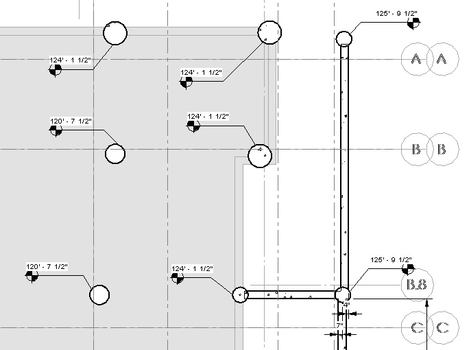
All the elements came into Revit right where they should be. The beams had physical and analytical components. (I haven’t figured out that quirk of ISM yet.) Anything that looked off, like a grid line that stopped halfway up the building, could be traced back to the RAM model element’s definition, not the import process. I estimate that it saved us at least 3 solid days of drafting/modeling time, if not more.

The catch with this second project is that it’s historic steel, not modern. So the RAM model had lots of substitutions for archaic shapes, which had to be swapped out in Revit to be properly displayed & tagged. So I don’t know yet if we’ll be able to round-trip the model. There might be some tweaks we can make to the mapping file to accommodate the historic shapes, but my research hasn’t gotten that far yet.

It’s a good start, though…onward and upward!

Quick Rotate Objects

01 Monday Apr 2013

Posted by Kate in Basics, Tips & Tricks

≈ Leave a comment

Tags

Columns, Revit, Rotate, Tips & Tricks

When you’re inserting objects or components into a Revit view, you may have noticed the “Rotate after placement” checkbox below the ribbon.QuickRotate1

It’s handy, I suppose, but personally, I haven’t used it since I discovered the quick-and-easy way to rotate objects before you place them: with the space bar.

By default, pressing the space bar before you place an object rotates it 90 degrees.

QuickRotate2 QuickRotate3

But if you hover over an existing object first, your new component will rotate to match its alignment.

QuickRotate4 QuickRotate5 QuickRotate6

I use this ALL the time for placing breaklines along braces and sloped beams, or to align columns with non-orthogonal grids.

Just a quick tip to tide you over while we wait for Revit 2014 to appear…

Autodesk Revit 2014

26 Tuesday Mar 2013

Posted by Kate in Announcements

≈ Leave a comment

Tags

Autodesk, News, Revit

Autodesk will be holding a webcast in about an hour (http://autode.sk/webcast) to announce the launch of their 2014 family of products, including Autodesk Revit. But some of the details are already out, and the product pages have been updated, so…let’s talk new software!

I wasn’t in the beta program this year, so I found out about the new features the regular way…through Twitter.

My lack of advance knowledge means I didn’t have a post loaded and ready to go for today.  But I’ve read enough to identify three quick favorite new features, all in the small-but-significant category.

  1. Non-rectangular view crops & callouts. This one will solve a problem that literally came up yesterday.
  2. Temporary view settings. I love view templates, and loved that they were made “sticky” in Revit 2013. But they can be annoying too, if you just need to see something briefly and turn it off again. Sounds like that annoyance is gone now.
  3. Multiple Bring-to-front/Send-to-back. Another annoyance removed. Now you can select multiple detail elements and change their view order, instead of working with one at a time.

I’m sure I’ll have more to say once I actually get the new version loaded on my machine. But if you’d like to read more today, David Light has excellent in-depth coverage, or you can visit the official Revit home page. Here’s a link straight to the structural new features.

Z-direction vs. Start & End offsets

25 Monday Mar 2013

Posted by Kate in Analysis, Framing, Tips & Tricks

≈ Leave a comment

Tags

Analysis, Beams, Revit, RISA

When you’re modeling structural framing in Revit, you often can just assign it to a level or reference plane to set its elevation.BeamOffset1

But sometimes you need to move a beam up or down — maybe to accommodate a slab step, architectural element, or other framing condition.

BeamOffset2

There are (at least) two ways to achieve the above image.

The first is with the z-Direction Justification and Offset. If you change Justification to “other”, you can then specify a single value to offset the beam up or down.

The second is with the Start and End Level Offsets. You can use these to give the two ends of the beam different elevations.

Which to choose? Well, it depends. Here’s what you need to know:

z-Direction Justification/Offset

  • The analytical line for a beam adjusted in the z-Direction stays put on the original reference level or work plane. This might be what you want to have happen, if you’re going to be exporting your analytical model to a program like RISA, or it might not. You’ll have to decide.BeamOffset3
  • You can only set one value, so it’s no good for sloped beams.
  • The z-Direction is relative to the beam, not the project. This means that if you have a beam with a rotated cross section, z-Direction offsets might not give you the result you’re looking for.BeamOffset4

Start & End Level Offsets

  • With this method, the analytical line follows your beam. Again, this may or may not create the desired effect with your analysis software.BeamOffset5
  • Each end can have a different offset, so you can create sloped framing.
  • HOWEVER, setting a start or end level offset AUTOMATICALLY detaches your framing from its work plane, and as far as I know you can’t get it back, even if the effect of the offsets keeps your framing parallel to its original plane.
  • Start/end offsets are relative to the level, so rotating your section keeps it more or less where it started. (Laterally, at any rate.)BeamOffset6

Combined Methods

  • You can actually use both methods at the same time for even more control over the location of your framing. Here’s the beam above with Start, End, AND z-Direction offsets.

 BeamOffset7

Keep Properties active

14 Thursday Mar 2013

Posted by Kate in Basics

≈ Leave a comment

Tags

Properties, Revit

Okay, some of you might laugh at this tip, it’s so simple. But it took me a little while to figure it out, and I saw somebody else get tripped up by it just last night, so I know it’s not just me.

Ready? Here it is:

The Revit Properties palette is only active while your cursor is over it.

Simple, right? But this happened several times a day until I caught on: Select an object to modify. Click on a field in Properties. Move the mouse out of the way. Press Delete to erase the current value. Realize the object disappeared instead. Mutter at the screen. Undo. Repeat.

The explanation for this is that Revit tracks the position of your cursor to determine whether the Properties palette is active. Moving the cursor off the palette has the same effect as clicking Apply — sometimes it’s even faster than using Apply.

Now that I know this, I’m more strategic with my cursor placement. I’ll move it up or down to get it out of the way of the field I’m editing, instead of left or right. When I’m finished, a quick flick to the side applies the changes. (I also made the palette a bit bigger, to give myself more room to move.)

For me, this falls under the category of “small but significant” features: easy to explain and use, but no less valuable for their simplicity. I’m sure there will be plenty more of these features in posts to come!

← Older posts

Recent Posts

  • First theme of AU2016? Connectivity
  • BIM Essentials Tip #3
  • RTC and AU and BIMThoughts, oh my!
  • Revit 2017!
  • AU2015, Day 3

Archives

  • November 2016
  • July 2016
  • April 2016
  • December 2015
  • November 2015
  • October 2015
  • July 2015
  • June 2015
  • May 2014
  • September 2013
  • August 2013
  • July 2013
  • May 2013
  • April 2013
  • March 2013
  • February 2013
  • January 2013

Categories

  • Analysis
  • Announcements
  • Autodesk University
  • Basics
  • BIM Essentials
  • Framing
  • IT
  • Podcasts
  • RTC
  • Standards
  • Thoughts
  • Tips & Tricks
  • Uncategorized
  • Views

Enter your email address to receive notifications of new posts by email.

 Subscribe in a reader

Create a free website or blog at WordPress.com.

Privacy & Cookies: This site uses cookies. By continuing to use this website, you agree to their use.
To find out more, including how to control cookies, see here: Cookie Policy
  • Follow Following
    • BIMmuse
    • Already have a WordPress.com account? Log in now.
    • BIMmuse
    • Customize
    • Follow Following
    • Sign up
    • Log in
    • Report this content
    • View site in Reader
    • Manage subscriptions
    • Collapse this bar
 

Loading Comments...